Come and take a tour of our machine in action! We will be making a G scale Baldwin disk wheel for the D&RGW M-68 Northern locomotive (4-8-4). This engine is being custom made for Gary Bartlow in San Diego by Doug Hemmeter at D&M Backshop in Houston, Texas. Pacific Locomotive Works was subcontracted to produce both Baldwin disk wheel masters and to get them cast in quantity for a total of 4 engines. Since our foundries could not handle the size of this wheel (they were the diameter of a CD or DVD!) we had to send them to Fenico Custom Castings in Los Angeles.
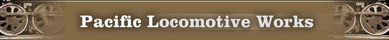
This is our SolidScape T-66 modeler, converted from the original green wax to the new BlueCast 2. It's about the size of a small dorm refrigerator. The printer is the top section, the middle section is for storage, and a small air conditioner is in the lower section to cool the wax after printing.
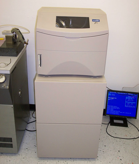
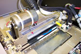
With the side door open, we can see part of the print head. A fair amount of time is spent here, with the door open; calibrating the amount of wax per layer, setting the registration, bubbling the heads (much like the plumbing in your house, a bubble is needed in the heads to avoid hammering). Additionally, you can see the tray on the bottom with wax chips in it. These are chips discarded from the head jet check. The heads are checked automatically before and after each layer built. The machine can detect if a layer went on bad, in which case it will cut it back and do it over. The roll of paper is used to clean the wax off the outside of the heads.
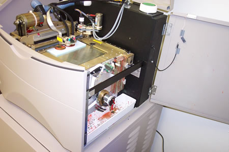
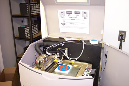
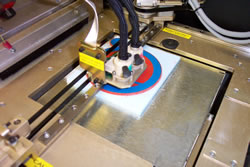
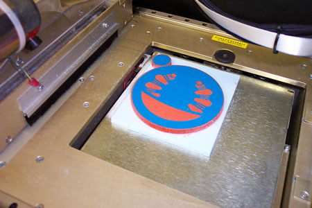
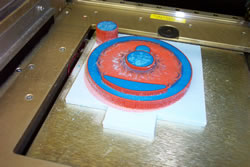
Here we find the machine beginning on the large M-68 Baldwin disk wheel. The stage can handle work 6" x 6" x 6", so it gives you an indication of the size. The blue foam is what we use to start a build on.
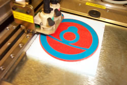
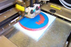
Close in we can see the heads printing the wheel. You will notice two different colored waxes. The blue wax (BlueCast 2) is our actual part, the red wax is a support wax to keep thin edges from cracking and filling out the model when it is is cut back. After each layer is laid down a milling cutter (you can see the big Pittman motor and belt) comes over and cuts the layer to the desired thickness. In our case. 0.001" on the backsides and 0.0005" on the frontsides. You will RARELY catch jewelers using layers this thin. They will typically step the model at between 0.001" and 0.003" (remember, they polish!) However, for the types of parts we produce, this thin layer gives us the best feature resolution. It does, however, dramatically increase build times (and cost!) Good thing the machine runs unattended!
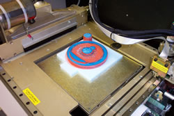
We now see the layer completed and the milling cutter coming across to trim back the layer. Actually, the print head carriage comes over and magnetically grabs the milling cutter and drags it across the model. A vacuum in the middle section of the cabinet draws up the cutter dust.
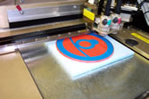
We now see our model cutback and ready for the next layer of wax and support!
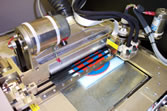
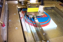
The next two pictures shows the print and support heads in action. They move so fast, they blur in the picture! Even though they move so fast, with the layers going on at 0.0005" the model can take a long time to build. In this case, this particular wheel took nearly 100 hours to build! That's over 4 days! Good thing it runs by itself.
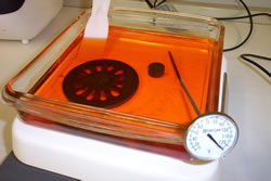
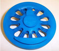
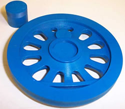
Finally, we can see the finished model, it's actually the light counterweight wheel in this case. You can see the little round cylinder in the background, that is the machining spud. This part is held by a collet on the lathe when turning the wheels. It is printed seperately and glued into place afterwards on the backside of the model (using model airplane glue.) Building this part seperately allows us to save wax (and money); otherwise the machine would have to build to the combined height of the wheel and the spud! The white dust is cutter dust.
Also notice the extra material extending from the hub. This extra material is needed incase the large combined mass of the hub and the machining spud cause axial shrinkage of the wax during casting of the production parts. The wax will shrink slightly in areas of large bulk, and the shrinkage can cause a divot in the hub area. The extra material ensures the shrinkage occur far outside the hub area, and then gets machined off later.
After all is done, the steel platen is removed from the machine and placed on a hotplate to soften up the adhesive on the blue foam. Then the blue foam is trimmed back with an X-Acto knife, and the model is placed in a bath of solvent to melt off the red wax. (Actually, this model was placed in a 100F oven for 6 hours to stress relieve it. Otherwise, it may have warped in the solvent bath.) The solvent is heated on a regulated hotplate at about 120-125F until all the red wax is dissolved. I have found out the hard way to change the solvent at regular intervals, as saturated solvent leaves enough residue on the model and cracks the investment flask during burn-out!
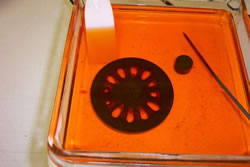
Lastly, the model is blown dry with compressed air (carefully!) and allowed to dry for a few days. It is then coated with baby oil (this helps for a smoother cast) and then sent off to the foundry for casting. On some models, we will supply sprue for the foundry to attach to, in some cases we let the foundry pick the best location for sprue.
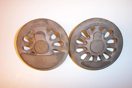
Finally, we see the masters once they were returned from the foundry.
Notice the lettering! These were cast in magnesium bronze (being they
cannot cast brass commercially in the LA basin...) The surface is a
coarse bead blast finish, which we told them not to do, but it actually
is a very nice finish, looking completely like a scale casting. The
machinist will almost half the weight of these castings in the machining
process (the rim gets cut down almost to the letters, the extended hub
almost flat to the hub and a skim cut on the counterweight.) The hubs
will be bored and broached for a quartering keyway, the crank pins machined
and pressed in, and the tires pressed on with Mylar insulation. Then
they are ready for paint and mounting on the locomotive!
Compare these wheels to the small photo in the lower left-hand corner
of the 1941 Locomotive Cyclopedia, page 685. That is all I had to work
from. Not bad, eh?